This is the CNC machine basic wiring diagram to step down the 415 VAC 3 phase power line to 240VAC single phase. To step down the 415 VAC 3 phase to 240 VAC 1 phase, I will take the L1 and N and connect them to 2 poles Miniature Circuit Breaker (MCB). The combination of L1 and N will generate 240 VAC single phase power line.

415 VAC to 240 VAC Step Down Circuit Diagram
L1 = R = Life 1
L2 = S = Life 2
L3 = T = Life 3
N = Neutral
E = earth or grounding
In the CNC machine, the 415 VAC 3 phase normally use by the CNC machine spindle motor. In fact, most CNC machine spindle motor can use whether 415 VAC 3 phase or 220 VAC 3 phase. The use of 240 VAC single phase is very seldom in CNC machine however some CNC machine retrofitter will use this power line to retrofit the CNC machine especially to power up the lamp and lubrication system but mostly depends on the industrial electrical components standard input power of each country or state.
When building a CNC machine, Earth Leakage Circuit Breaker (ELCB) and MCB must be used to ensure all the CNC electrical and electronic components are well protected. For extra protection, fuses are also will be used. I myself use ELCB range from 40 Amp to 80 Amp, MCB range from 20 Amp to 32 Amp and fuses range from 10 Amp to 20 Amp.
415VAC 3 Phase to 240Vac Single Phase
220VAC 3 Phase to 110VAC Single Phase
Nowadays, most CNC machines are using 220VAC 3 phase power supply to power up the spindle motor and other electrical components such as coolant motor and inverter. Other electrical components like lamp and servo drive are using 110VAC power supply, then in this case you need to step down the 220VAC 3 phase to 110VAC single phase.
Diagram below is showing you the simple technique to convert or step down the power line 220VAC 3 phase to 110VAC single phase. In order to convert the 220VAC 3 phase power supply into 110VAC 1 phase, you need to use proper electrical components such as Earth Leakage Circuit Breaker (ELCB) and 2 poles Miniature Circuit Breaker (MCB). You are strongly recommended to use some fuses to protect any electrical components on your CNC machine.
Centroid AC Servo Motor Wiring Diagram

High inertia Centroid AC Servo Motor type HJ130C8-64S with maximum 4000 RPM, 5.7NM torque, 34A and 260V input power make it suitable to retrofit medium size CNC milling machine. This servo motor is typically use to retrofit the milling machine x-axis and y-axis. Scroll down to get details info about the servo motor wiring diagram especially the encoder pins and the power supply pins
Centroid servo motor female encoder pin connector. The female connector has 17 pins
Male servo motor encoder pin connector
Servo motor 4 pins female power connector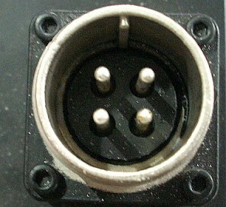
Servo motor male power connector; U, V, W and grounding or shield 
The Centroid AC servo motor wiring diagram for encoder pin connector and power supply connector
Encoder pin connector symbol