Showing posts with label G Codes. Show all posts

CNC Machine Codes, Terms and Definitions

List of CNC Machine Codes, Terms and Definitions. Some of the codes, terms and definitions might be difference between manufactures for difference type of machine and machine controller.

A-axis = Capability of machining tools moving in circular motion around x-axis

B-axis = Capability of machining tools moving in circular motion around y-axis

C-axis = Capability of machining tools moving in circular motion around z-axis

X-axis = Capability of machine tools moving in the x-axis direction
Y-axis = Capability of machine tools moving in the y-axis direction
Z-axis = Capability of machine tools moving in the z-axis direction
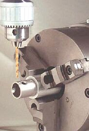
CNC machine codes, terms and definitions

D code = Tool diameter offset number
E code = Selection of work coordinate system. Equivalent to G54 to G59
F code = Feedrate
G code = A CNC program code that determines the type of operation to perform

H code = Tool length offset number
I code = Absolute center of arc in x-axis
J code = Absolute center of arc in y-axis
K code = Absolute center of arc in z-axis
L code = The number of repetition of a cycle
M code = The program code that control overall machine function
N code = Block number
O code = The program number allows you to identify your program with a certain number

P code = Parameter
Q code = Depth of cut parameter in canned drilling cycles
R code = Represent the radius, a return point or a general parameter
S code = Spindle speed
T code = Tool number
U code = Relative axis parallel to x-axis
V code = Relative axis parallel to y-axis
W code = Relative axis parallel to z-axis
X code = Absolute machine tool position on x-axis
Y code = Absolute machine tool position on y-axis
Z code = Absolute machine tool position on z-axis

Lathe Machine G Codes

The CNC Lathe Machine G Codes

G00 Rapid position
G01 Linear interpolation
G02 Circular or helix interpolation CW
G03 Circular or helix interpolation CCW
G04 Dwell
G10 Parameter setting
G20 Select Inch units
G21 Select Metric units
G28 Return to reference point
G29 Return from reference point
G30 Return to secondary reference point
G32 Constant lead thread cutting
G40 Cutter compensation cancel
G41 Cutter diameter compensation left
G42 Cutter diameter compensation right
G50 Coordinate system setting, Max spindle speed setting
G52 Offset local coordinate system
G53 Rapid position in machine coordinates
G54 Select working coordinate system #1
G55 Select working coordinate system #2
G56 Select working coordinate system #3
G57 Select working coordinate system #4
G58 Select working coordinate system #5
G59 Select working coordinate system #6
G54 P1 Select working coordinate system #7
G54 P2 Select working coordinate system #8
G54 P3 Select working coordinate system #9
G54 P4 Select working coordinate system #10
G54 P5 Select working coordinate system #11
G54 P6 Select working coordinate system #12
G54 P7 Select working coordinate system #13
G54 P8 Select working coordinate system #14
G54 P9 Select working coordinate system #15
G54 P10 Select working coordinate system #16
G54 P11 Select working coordinate system #17
G54 P12 Select working coordinate system #18
G65 Call macro
G70 Finishing cycle
G72 Stock removal in facing
G74 End face peck cutting
G75 Outer/inner diameter peck cutting cycle
G76 Multi-pass threading cycle
G80 Canned cycle cancel
G83 Deep hole drilling
G84 Tapping
G85 Boring cycle
G90 Outer/inner diameter cutting cycle
G92 One-pass threading cycle
G94 End face cutting cycle
G96 Constant surface speed
G97 Constant surface speed cancel
G98 Per minute feed
G99 Per revolution feed

Milling Machine G Codes

The G Codes that use on most CNC Milling Machines Center.

G00 = Rapid position
G01 = Linear interpolation
G02 = Circular or helix interpolation CW
G03 = Circular or helix interpolation CCW
G04 = Dwell
G09 = Exact stop
G10 = Parameter setting
G17 = Circular interpolation plane selection XY
G18 = Circular interpolation plane selection ZX
G19 = Circular interpolation plane selection YZ
G20 = Select Inch units
G21 = Select Metric units
G28 = Return to reference point
G29 = Return from reference point
G30 = Return to secondary reference point
G40 = Cutter compensation cancel
G41 = Cutter compensation left
G42 = Cutter compensation right
G43 = Tool length compensation (+)
G44 = Tool length compensation (-)
G49 = Tool length compensation cancel
G50 = Scaling/mirroring OFF
G51 = Scaling/mirroring ON
G52 = Offset local coordinate system origin
G53 = Rapid position in machine coordinates
G54 = Select working coordinate system #1 (WCS #1)
G55 = Select working coordinate system #2 (WCS #2)
G56 = Select working coordinate system #3 (WCS #3)
G57 = Select working coordinate system #4 (WCS #4)
G58 = Select working coordinate system #5 (WCS #5)
G59 = Select working coordinate system #6 (WCS #6)
G61 = Exact stop mode
G64 = Cutting mode
G65 = Call macro
G68 = Rotate
G69 = Cancel rotate
G73 = High speed peck drilling
G74 = Counter tapping
G80 = Canned cycle cancel
G81 = Drilling and spot drilling
G82 = Drill with dwell
G83 = Deep hole drilling
G84 = Tapping
G85 = Boring
G89 = Boring with dwell
G90 = Absolute positioning mode
G91 = Incremental positioning mode
G92 = Set absolute positioning
G98 = Initial point return
G99 = R point return
G117 = Rotation of plane selection XY
G118 = Rotation of plane selection ZX
G119 = Rotation of plane selection YZ

What is CNC ?

What is CNC? Basically, the CNC stands for Computer Numerical Control which refers to a computer controller that controls the movement of every axis of the machine using G codes instructions and drives the spindle or machine tool into a raw material to fabricate or to remove the unwanted material from workpiece more accurately without human intervention.

Centroid CNC milling machine controller
High performance and user-friendly CNC controller for milling applications
Photo by Centroid CNC


Fully integrated CNC machines will use G codes, M codes and others CNC programming languages codes such as F, S, N, X, Y, Z, A, B and C codes to control the overall machine.

G codes is a common name in the CNC programming language that begins with the letter G. Basically, the G codes tell the machine tool what type of action need to perform and trigger the CNC machine tools axis movement.

Typically, the CAM software such as Edgecam, Bob-CADCAM, Alphacam, MasterCAM, ProCAM 2, SurfCAM, Artcam and DelCAM may be used to generate the G codes files. The translators called post-processors will optimize the G codes output and it's user editable for further customization if needed.

The CNC milling machine simple programming language that use G codes and other CNC codes to perform drilling some holes and milling a circle pocket clean out.

; ICN_PATH = c:\intercon\test-run1.icn
; --- Header ---
N0001 ; CNC code generated by Intercon v2.61 Dev Test, Rev 8
; Description: test
; Programmer: vast
; Date: 11-Sep-2008
M25 G49 ; Goto Z home, cancel tool length offset
G17 G40 ; Setup for XY plane, no cutter comp
G21 ; millimeter measurements
G80 ; Cancel canned cycles
G90 ; absolute positioning
G98 ; canned cycle initial point return
; --- Tool #5 ---
;Tool Diameter = 6.0000 Spindle Speed = 1000
;d5
G49 H0 M25
G0 X0.0 Y0.0
N0002 T5 M6
S1000 M4
M8
G4 P1.00 ; pause for dwell
G43 D5
; --- Drill BHC ---
N0003 X20.0 Y0.0 Z2.54 H5
G81 X20.0 Y0.0 Z-1.0 R2.5 F100.0
X12.47 Y15.637
X-4.45 Y19.499
X-18.019 Y8.678
X-18.019 Y-8.678
X-4.45 Y-19.499
X12.47 Y-15.637
G80
; --- Circ Poc ---
N0004 X200.0 Y-1.0 Z2.54
G1 G91 X0.0 Y0.0 Z-2.54
X0.0 Y0.0 Z0.0 F300.0
X0.0 Y1.0 Z-1.0 F100.0
G2 X0.0 Y3.5 Z0.0 J1.75 F300.0
X-3.5 Y-3.5 Z0.0 J-3.5
X3.5 Y7.0 Z0.0 I8.75
X0.0 Y0.0 Z0.0 J-7.0 F400.0
X0.0 Y-7.0 Z0.0 J-3.5
G0 G90 X200.0 Y0.0 Z2.54
; --- End Prog ---
N0005 G49 H0 M25
X200.0 Y0.0
G40 ; Cutter Comp Off
M5 ; Spindle Off
M9 ; Coolant Off
G80 ; Cancel canned cycles
M30 ; End of program

The G codes generated by CENTROID's Intercon Conversational software used in Centroid CNC Milling Machine controller