EMCO offers you top European technology at the best possible price. C-axis, a bar loader package, your choice of SIEMENS or FANUC control unit and much, much more. And all that in the highest quality. For precision parts and a long machine life.
CNC Turning Center Machine Videos
Watch Turning Center Video
Matsuura 5 Axis Machining Center
Watch V8 engine block being machined from solid workpiece using high speed and high accuracy Matsuura 5-axis machine center
V8 Engine Block Machined From Solid
Presented by Matsuura
Laser Cutter
A Laser cutter is a machine tool that uses a laser to cut a workpiece such as ferrous metals, non-ferrous metals, stone, plastics, rubber, ceramics, and many other soft materials. A laser cutter works by focusing a high power laser beam at a specific location on the surface of the workpiece. The energy in the laser beam is absorbed into the surface of the workpiece, and converted into heat. The energy density in the laser beam is extremely high, it is enough to melt or vaporize the surface of the workpiece. The melting surface will be propagated until the workpiece is cut through.
Articulated laser cutter arm - 6 axes of motion
Photo by Mundt Inc
CNC Laser Cutting Machine
Photo by Madewell Products Limited
Laser Cutter Machine
Photo by Vance Metal Fabricators, Inc
CNC Surface Grinding Machine
What is CNC surface grinding machine? A CNC surface grinding machine is a machine tool uses for producing micron-precise or ultra-fine finishes on tough workpiece and extremely accurate surface finishing with maximum precision and short cutting times. The surface finishing process will be performed by a rotated abrasive wheel which will remove the access metal from the surface of the workpiece. The abrasive wheels can be made up of various sizes and types of stones, diamonds or inorganic materials.
CNC surface grinding machine excels with repetitive, tedious and complicated parts, combines with extremely effective operation of conventional surface grinding machine with the user-friendliness and precision of modern CNC controller, servo drive and measuring systems. Normally the surface grinding machine is used for final machining process to the workpiece which has been machined by other method to get high accuracy in dimension of the workpiece.
Internal cylindrical grinding 
External cylindrical grinding
Surface grinding final result
Photos by Leech Industries, Inc.
Surface grinding machine is also used to grind very hard workpiece especially the harden workpiece such as tools, dies and punches. CNC Surface Grinding Machine has the capability to grind flat surfaces, angular surfaces, concave & convex surfaces or centreless surfaces, external & internal cylindrical surfaces, round surfaces and cone surfaces.
CNC Surface Grinding Machine
NC Surface Grinding Machine
Photos by Ching Hwee International Trading Co., Ltd.
Indian Waterjet Cutting Machine
Watch the Indian Waterjet Cutting Machine video
Presented by Ainnovative Technologies
CNC Waterjet Cutting Machine
What is Waterjet Cutting Machine? A Waterjet Cutting Machine is a machine tool uses a specific and a consistent high pressure pressurized water called waterjet which supplied by high pressure pump to cut or pierce variety of metal or non-metal materials.
CNC Waterjet Cutting Machine is consistently deliver an extremely high level of cutting precision, accuracy and performance that fully utilize the waterjet cutting technology which uses CNC G codes and CNC M codes to control the overall machie cutting process.
There are two type of waterjets used by Waterjet Cutting Machines to cut materials. There are Pure Waterjet and Abrasive Waterjet. A Waterjet Cutting Machine might used pure waterjet or abrasive waterjet or both method to cut almost any materials. Pure waterjet uses to cut a variety of soft materials such as paper, rubber, foam and baby diapers. The abrasive waterjet uses to cut almost any hard materials such as titanium, stainless steel, stone and glass.
How a Waterjet Cutting Machine Works?
How Waterjet Cutter works? Basically, the Waterjet Cutter or Waterjet Cutting Machine uses the technology of high pressurized water supplied by high pressure pump and delivers it consistently and continuously up to 90,000 psi or 6200 Bar (620 MPa) and forced it through a pre-mounted orifice or small hole as small as 0.005 inches (0.127 mm), it will create a jet stream called pure waterjet.
Pure Waterjet
If a small amount of abrasive material such as granet is mixed into the jet stream, it will create a jet stream called abrasivejet or abrasive waterjet. The jet stream flow exits the nozzle will make contact with the surface of workpiece. The workpiece will develop small cracks due to jet stream impact and propagate until the material is cut through.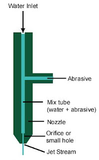
Abrasive Waterjet

CNC Waterjet Cutting Machine - JETMax HS 4020
Photo by Maximator JET GmbH
How to Retrofit A Machine?
How to retrofit a machine? Basically, to retrofit or to upgrade a machine you need to remove the old control components especially the machine controller, motor driver, motor of each axis, the lead screws for manual machine, lubrication system if necessary, and the electrical cabinet if necessary. In fact, to retrofit a machine can be divided into two main categories, to retrofit the manual machine and to retrofit the old CNC machine.
A. Retrofit The Manual Machine
These are the components need to replace or need to add in order to retrofit the manual machine:
1. The old controller need to be replaced with CNC controller
2. Motor driver need to replace with servo drive
3. Motor of each axis (X, Y & Z) need to be changed with servo motors
4. Lead screws will be replaced with precision ballscrews
5. Manual lubrication system need to change with auto lubrication system
6. If the machine not equipped with coolant system then coolant system need to add
7. The electrical cabinet might need to be changed if necessary
8. Change the power supply with transformer for bigger KVA or with other power supply
9. Retain the original ELCB, MCB, contactors, terminal block and fuses if possible
10. Inverter need to be added to control the spindle motor if necessary
11. Retain the light system if necessary
12. The machine and electrical cabinet need to re-wiring
13. Repaint the machine if necessary (optional)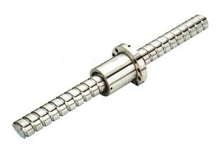
Precision Ballscrew
B. Retrofit The CNC Old Machine
These are the components need to replace or need to add in order to retrofit the old CNC machine:
1. Old CNC controller need to change with new CNC controller
2. Servo drive need to change with the new servo drive
3. Servo motor for X, Y and Z axis need to change with new servo motors
4. The PLC need to add if the servo drive doest not have enough I/O
5. Retain the Inverter for spindle motor if possible
6. Retain the electrical cabinet if possible
7. Retain the transformer or power supply if possible
8. Retain the original ELCB, MCB, contactors, terminal block and fuses if possible
9. Retain the precision ball screw if possible
10. Retain the lubrication system, coolant system and hydraulic system if possible
11. Retain the light system if possible
12. Re-wiring the machine and electrical cabinet
13. The spindle motor can be change if need more RPM (optional) - costly
14. Repaint the machine (optional)
Emerson Inverter for Machine Retrofit
What is CNC Retrofit?
What is CNC retrofit? The CNC retrofit is machine rebuilding, upgrade or giving new life to the old machines whether the old cnc machines, the old manual machines or the unused machines. Machine retrofit is important especially to those machines facing high downtime due to a poor machine performance and the machine are getting too old and breakdown become more frequently. In fact, certain cases the CNC retrofitting will also take place due to limited capability of the machines especially the manual machines.
Downtime will cause a lot of delay in the work flow and it will cause a lot of headaches for a lot of people. Any downtime will cause serious losses and will cause huge loss of revenues as well. Certain machines could have excessive downtime due to a high frequency of maintenance, which may support the decisions to upgrade or retrofit ineffective machine that continues to adversely affect the bottom line and make the production more costly. Sometimes downtime occurred due to improper maintenance, low lubricant levels, high operating temperatures and other factors.
CNC retrofitting will be done by converting the manual machine into CNC machine or by replacing existing CNC controller with a new more flexible, and powerful latest generation CNC controller to increase the machines machining capabilities with the most cost effective way to suit your needs. Cost effective retrofit that help you to maximize your productivity. The retrofit provides superior machining capability for much less than the purchase price of a brand new machine.
The retrofit possible benefits include:
* Improve the machine flexibility up to 5 axis or more
* Improve machine accuracy and grad of machining
* Easy and flexibly parts programming and machining
* Equipped with USB port, RS323 port and Local Area Networking (LAN)
* Easy to edit, modify, download and upload programming file
* Reduce machine downtime and maintenance cost
* Easy machine trouble shooting
* Reduce parts damage and scrap
* Link the CNC controller with the computer network
* Increase the workers confident level and moral
* Easy to automate the retrofitted machine with the production line
Machines are suitable to retrofit included:
1. Milling machines
* Knee mill, bed mill or ram mill type
* Vertical machining center or horizontal machining center
2. Lathe machines
* Manual lathe machine
* Horizontal tuning center or vertical tuning center
3. Router machines and
4. Water jet cutting machines
5. Other machines
What is EDM?
What is EDM? The EDM is stands for Electrical Discharge Machining or Electrical Discharge Machine. Other popular name for EDM is Electro Discharge Machine. There are two most popular EDM machine, Ram EDM Machine and EDM Wire Cut. Ram EDM also known as, Sinker EDM, Die Sinker, Vertical EDM or Plunge EDM. Ram EDM divided into two main categories, Conventional EDM and CNC EDM. EDM is a non conventional machining method to remove unwanted material from electrically conductive workpiece or metal. EDM is a machining method primarily used for hard metals, super-tough alloy, hardened materials or cutting delicate cavities that would be impossible to machine with conventional machining method such as milling, drilling, grinding or with other type of conventional machine tools. Some of the EDM applications are machining aerospace alloys such as titanium, inconel, & hastalloy, removing broken taps, drills, & bolts and machining of carbide dies and tools..jpg)
Conventional EDM or EDM Ram Type
How EDM works? Basically, the EDM process is simple the unwanted material removes by use of recurrent sparks applied to a hard metal. An electrical discharge is created between an electrode and the workpiece known as spark to create spark gap or spark erosion between the electrode and workpiece. For Ram EDM, a special brass will be fabricated into a desire shape and use it as an electrode. The brass will be attached to the EDM machine and use it to machine the workpiece under carefully controlled conditions. Read this blog post about Wire Cut EDM for more details information.
CNC Electrical Discharge Machine / CNC EDM
Photos by Creator Precision co., Ltd
During EDM process, the current will be switched on and off by moving the electrode up (current off) and down (current on) to control the spark gap. When the current is switched on the spark jumps across the gap and the small amount of unwanted material is removed from the workpiece to allow the electrode to be moved through the workpiece. The electrical spark are very short in duration, approximately 1 microsecond to 1 millisecond each. This process repeats its self over and over again until the electrode is slowly advanced deeper and deeper into the cut. The path of the electrode is typically controlled by a numerical controller (NC) for NC EDM machine or computer numerical controller (CNC) for CNC EDM machine, which allows a desire shapes to be produced.
The spark always takes place in the dielectric of deionized fluid which acts as a coolant and when the current is switch off the deionized fluid will flushes away the eroded particles from the workpiece. In fact, the electrode itself does not touch the workpiece being cut because the actual cutting is being done by the electrical discharge or spark created between the electrode and the workpiece.
What is CNC Router Machine?
What is CNC Router? The CNC Router is a multipurpose machine. This machine is used to cut wood, plastic or metal, as well as engrave or route out letters on signs. The CNC router is an amazing machine that can do seemingly almost anything, so you can get a lot of usage from this machine. Many small fabrication shops, and even individuals are finding the accuracy and versatility of a CNC Router is very useful. The CNC Router is great for hobbies, engineering prototyping, product development, art, robotic education, production work, furniture, advertisement and other fields.
The 6000 series CNC Router Machine
Photo by AXYZ Automation Inc
The 6000 series CNC Router Machine applications including
* Plastic fabrication
* Education
* Aircraft manufacture
* Mould making
* Wood working
* Sign making
* Solid surface
* Boat building
* RV manufacturing
* Metal working
* Engineered composite panels
A CNC Router machine has a similar operation with a plotter and controls by a computer. The CNC Router works on the 3D motion control to make high quality parts for you. Basically, the CNC Router has three axes X, Y and Z. Each axis will be motorized with stepper motor or servo motor that drives the router via a gantry system to form a 3 axis CNC Router machine.
Normally, the CNC Router machine will be supplied with a powerful software to do your design or drawing. You draw your work on the computer and convert it to G codes then send your drawing to the CNC controller for final result in 3D. The CNC controller will command the CNC Router machine to make the desired parts for you, quickly and accurately. Most CNC router software will convert your drawing into G codes automatically before send to CNC router machine via router CNC controller. This makes CNC Routers ideal for woodworking, plastic molding, advertisement fields and aerospace industry.
What is CNC Controller?
What is CNC Controller? The CNC controller is an important part of CNC machine tools. It is the heart of any CNC machines system. A CNC controller connects all the important link between a computer system and the electrical components on the CNC machine such as the servo motors, spindle motor, coolant motor, lubrication motor and other electrical components. The main function of the CNC controller is to run the electrical components on the CNC machine tools to drive the mechanical parts on the CNC machine or to control the multiple axes on the machine.
Centroid CNC Controller
Basically, to drive the mechanical components on the CNC machine, the CNC controller will work side by side with CPU unit, computer systems, servo motor drive, motion controller, PLC unit and inverter to form a sub-field of automation to determine the tool position on each axis, moving velocity of each axis, spindle speed and to run other electrical components such coolant pump, hydraulic pump, lubrication pump and light.
In fact, the powerful CNC controller does far more than drives the motors which some of the controllers have the capabilities to detect and control the limit switches, the coolant flow amount, air pressure, hydraulic pressure, detect temperature, detect and run up to 200 tool positions and more. CNC Controls enhance the machine's productivity capabilities with a new level of easy-to-access information and programming tools. Some of the CNC controller systems are available for a wide-range of applications such as grinding, drilling, digitizing, engraving, probing, cutting, milling, punching, turning and many more.
Nowadays, the modern CNC controllers range from professional stand alone system built-in with keyboard and user interface to hobby use CNC controllers that require a personal computer. The modern controllers come with CNC software packages such as Computer Aided Design (CAD) software, Computer Aided Manufacturing (CAM) software and the Computer Numerical Control software. The CAD is used for displaying and editing designs on the computer. The CAM is used to convert the geometry into tool paths or computer numerical codes called G codes that can be understood by the machine tools. The Computer Numerical Control software will control the machine tools to physically cut your 2D or 3D workpiece in real time.
Most of the CNC controllers in the market are provided with the user interface such as RS232 port, USB flash memory port and LAN port. It is easier to transfer the cnc programs and any files from computers or USB flash memory to CNC controller. LAN port can be connected to router or Hub to establish the connection between the controller and other computers. Using RS232 you can transfer or modify any files on controller from other PC or laptop.
Most of CNC Controllers are equipped with
* USB port to download and upload the files between controller and USB flash memory
* RS232 port to connect the controller with a personal computer (PC) or laptop
* LAN port to connect the controller with other computers
* Probe port to auto set the tool height offset and set tool reference point
* Axis buttons to control the movement of each axis on the machine
* MPG port
* Feedrate button to control the velocity of machine tools
* Speed control (FAST/SLOW) button when moving the axis
* Spindle adjustable speed button
* Spindle CW and CCW buttons
* Spindle ON/OFF button
* Auto and manual function buttons for spindle and coolant
* Coolant ON/OFF button
* Tool Check button
* Tool path viewer and cut-time estimation
* Single mode button to run the machine tool block by block program number
* Light ON/OFF button
* Incremental button 0.1, 0.01 and 0.001
* Start, stop, repeat on any line of G-code
* Emergency stop button
* and much more
List of CNC Machines
These are the List of CNC Machines or the Type of CNC Machines that are commonly available in the market. Anyway, sometime it is too hard and bit confusing to categorize some type of CNC machines due to too many capabilities built-in one machine such as combination of milling, turning, and grinding capabilities.
In fact, some of the CNC machines deliver an awe-inspiring combination of features that yield speeds, feeds and surface finishes that have never been seen before. But I believe, the way to categorize the type of CNC machines equipment and tools will be drastically changed by reading this article.
Here are the List of CNC Machines by the type of CNC Machines
(This machines list is not a comprehensive CNC Machines list)
CNC Milling Machine Center
• CNC Vertical Milling Machine or Vertical Machining Center (VMS)
• CNC Horizontal Miling Machine or CNC Horizontal Machining Center (HMC)
CNC Lathe Machine Center or CNC Turning Machine Center
• CNC Vertical Turning Machine Center
• CNC Horizontal Turning Machine Center
CNC Cylindrical Grinding Machine
CNC Router Machine
CNC Plasma Cutting Machine
CNC Water Jet Cutting Machine
• CNC Pure Waterjet Cutting Machines
• CNC Abrasive Waterjet Cutting Machines
CNC Electro Discharge Machine (EDM)
• CNC EDM Wire Cut Machines
• CNC Ram Type EDM
CNC Foam Cutter Machine
CNC Surface Grinding Machine
CNC Welding Machine
CNC Turret Punch Machines
CNC Press Brake Machines
CNC Tube Bender Machines
CNC Forming Machines
CNC Bending Machines
CNC V Cut Machines
CNC Hydraulic Guillotine Shear Machines
CNC Lifting Table Panel Sizing Machines
CNC Laser Cutting Machine
CNC Woodworking Machine
Mini CNC Machines or Small CNC Machines
Hobby CNC Machine
Gear CNC Machine
Wheel Rim CNC Machine
CNC Machine Codes, Terms and Definitions
List of CNC Machine Codes, Terms and Definitions. Some of the codes, terms and definitions might be difference between manufactures for difference type of machine and machine controller.
A-axis = Capability of machining tools moving in circular motion around x-axis
B-axis = Capability of machining tools moving in circular motion around y-axis
C-axis = Capability of machining tools moving in circular motion around z-axis
X-axis = Capability of machine tools moving in the x-axis direction
Y-axis = Capability of machine tools moving in the y-axis direction
Z-axis = Capability of machine tools moving in the z-axis direction
D code = Tool diameter offset number
E code = Selection of work coordinate system. Equivalent to G54 to G59
F code = Feedrate
G code = A CNC program code that determines the type of operation to perform
H code = Tool length offset number
I code = Absolute center of arc in x-axis
J code = Absolute center of arc in y-axis
K code = Absolute center of arc in z-axis
L code = The number of repetition of a cycle
M code = The program code that control overall machine function
N code = Block number
O code = The program number allows you to identify your program with a certain number
P code = Parameter
Q code = Depth of cut parameter in canned drilling cycles
R code = Represent the radius, a return point or a general parameter
S code = Spindle speed
T code = Tool number
U code = Relative axis parallel to x-axis
V code = Relative axis parallel to y-axis
W code = Relative axis parallel to z-axis
X code = Absolute machine tool position on x-axis
Y code = Absolute machine tool position on y-axis
Z code = Absolute machine tool position on z-axis
CNC MPG Pendant
The MPG is stands for Manual Pulse Generator and also known as Jog Wheel Control or Remote MPG Handwheel. MPG is the CNC Machine tool remote control to jog any axis on the CNC machine. The MPG is designed for use in industrial CNC environments to make the man-machine interface safer, easier and faster. The MPG will hopefully makes manual jogging easy, smooth, precise and eliminates the need of axis buttons on the CNC controller.
CNC MPG Pendent
The Axis Selector (top) and Micrometer Wheel (bottom)
The micrometer wheel which is located at the bottom of the MPG allows you to position any axis in a minimum increments of approximately 1 micron (0.001 mm or 0.0002"). The Axis Selector allows you to select any axis and manually jog the axis using the MPG. It is great to use it during tools height offset setting and setting up the part zero positions on the large CNC machine fast and easy.
The MPG itself was ergonomically designed that is easy to hold. Come with convenient hanger which can be mounted on the CNC controller or anywhere it is convenient and it also contains strong magnets in the base for mounting to steel surfaces.
Some of the MPGs might equipped with these
* Emergency Stop Switch
* LED Status Indicator
* Cycle Start push Button
* Cycle Hold Push Button
* Feed rate override control
* Axis Reference Push Button
* Spindle On/Off Push Button
* Enable Push Buttons
Lathe Machine G Codes
The CNC Lathe Machine G Codes
G00 Rapid position
G01 Linear interpolation
G02 Circular or helix interpolation CW
G03 Circular or helix interpolation CCW
G04 Dwell
G10 Parameter setting
G20 Select Inch units
G21 Select Metric units
G28 Return to reference point
G29 Return from reference point
G30 Return to secondary reference point
G32 Constant lead thread cutting
G40 Cutter compensation cancel
G41 Cutter diameter compensation left
G42 Cutter diameter compensation right
G50 Coordinate system setting, Max spindle speed setting
G52 Offset local coordinate system
G53 Rapid position in machine coordinates
G54 Select working coordinate system #1
G55 Select working coordinate system #2
G56 Select working coordinate system #3
G57 Select working coordinate system #4
G58 Select working coordinate system #5
G59 Select working coordinate system #6
G54 P1 Select working coordinate system #7
G54 P2 Select working coordinate system #8
G54 P3 Select working coordinate system #9
G54 P4 Select working coordinate system #10
G54 P5 Select working coordinate system #11
G54 P6 Select working coordinate system #12
G54 P7 Select working coordinate system #13
G54 P8 Select working coordinate system #14
G54 P9 Select working coordinate system #15
G54 P10 Select working coordinate system #16
G54 P11 Select working coordinate system #17
G54 P12 Select working coordinate system #18
G65 Call macro
G70 Finishing cycle
G72 Stock removal in facing
G74 End face peck cutting
G75 Outer/inner diameter peck cutting cycle
G76 Multi-pass threading cycle
G80 Canned cycle cancel
G83 Deep hole drilling
G84 Tapping
G85 Boring cycle
G90 Outer/inner diameter cutting cycle
G92 One-pass threading cycle
G94 End face cutting cycle
G96 Constant surface speed
G97 Constant surface speed cancel
G98 Per minute feed
G99 Per revolution feed
Lathe Machine M Codes
The CNC Lathe Machine M codes
M00 Stop for operator
M01 Optional stop for operator
M02 Restart program
M03 Spindle ON CW
M04 Spindle ON CCW
M05 Spindle OFF
M07 Mist coolant ON
M08 Flood coolant ON
M09 Coolant OFF
M10 Clamp ON
M11 Clamp OFF
M13 Cutoff
M16 Chuck ID selection
M18 Chuck OD selection
M22 Extend part chute
M23 Retract part chute
M29 Set trap for G84
M32 Tailstock quill forward (out)
M33 Tailstock quill retract (in)
M34 Part catch forward
M35 Part catch retract
M41 Select spindle #1
M42 Select spindle #2
M46 Door open
M47 Door close
M50 C axis disable
M51 C axis enable
M91 Move to minus home
M92 Move to plus home
M93 Release motor power
M94 Turn ON input X
M95 Turn OFF input X
M98 Call subprogram
M99 Return from subprogram
M100 Wait for input to open
M101 Wait for input to close
M102 Restart program
M103 Programmed action timer
M104 Cancel programmed action timer
M105 Move minus to switch
M106 Move plus to switch
M107 Output BCD tool number
M108 Enable override control
M109 Disable override control
M115 Protected probing move
M116 Protected probing move
M120 Open data file (overwrite existing file)
M121 Open data file (append to existing file)
M122 Record position(s) and/or comment in the data field
M123 Record value and/or comment in data field
M125 Protected probing move
M126 Protected probing move
Lathe Machine
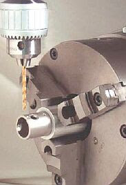
What is lathe machine? A Lathe Machine also known as Turning Machine which operates by rotating a workpiece about its axis to perform various machining operations such as cutting, drilling, reaming, tapping, parting, facing, threading, knurling and perform other operations. A single point cutting tool is fed against the rotated workpiece to remove the excess material or unwanted material to form a cylindrical shaped product. With a proper attachments and adjustments, a lathe can also bore, polish and grind. The variety of operations that lathe can perform make it one of the most useful and necessary machines in the market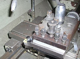
Lathe Single Point Cutting Tool
Lathe Cutting Tool Carriage
The lathe operates on the principle of the work being rotated against the edge of a cutting tool. The major function of the lathe machine is to change the size and shape of a rotated workpiece by one cuts or a series of cuts with cutting tools that can be adjusted to the workpiece. The cutting tool is controllable and can be moved lengthwise on the lathe bed and into any desired angle across the rotated workpiece.
Manual turning machine also known as a conventional lathe machine or turning machine and the cutting operation is partially control mechanically or can be fully controlled manually which is designed to produce parts within an accuracy range of 0.01 mm. The ultra-precision turning machine is known as CNC Turning Machine. It has high levels of accuracy and repeatability which operates in micron ranges and this machine has a dimensional accuracy ten times better than a conventional lathe.
Manual Turning Machine
Precision CNC Turning Machine
Photos by Republic Lagun Machine Tool
CNC Plasma Cutter Machine
What is CNC Plasma Cutter? A CNC Plasma Cutter is a machine or a device uses to cut metal such as mild steel, aluminum, stainless steel or any other electrically-conductive metals by using a powerful electric arc and a gas such as a compressed air. The compressed air blows the arc through the metal at 20,000 feet per second and at the temperatures as high as 30,000 degrees Fahrenheit creating a fairly clean cut or with little slag.
If you boost a gas normally a compressed air to extremely high temperatures, you will get plasma. In this process the compressed air is blown at high speed out of a nozzle. An electrical arc generated by the torch electrode will be forced through that gas and turning some of that gas to plasma. The force of the plasma flow then literally blows out the molten area on the workpiece, leaving only a smooth clean edge behind or with a little slag. Plasma can also be used for plasma arc welding and other applications.
A CNC Plasma Cutter has a similar operation with a plotter and controls by a computer. It has three axes X, Y and Z. Stepper motor or servo motor will drive each axis and work together, going forward & backward, left & right and up & down in perfect synchronization to produce shapes of virtually any design.
AKS Tru-Kut CNC Plasma Cutter
AKS Tru-Kut is one of the Advanced Kiffer Systems, Inc product. It's extremely heavy-duty, rigid, high quality construction with versatile features and affordable price make AKS Tru-Kut CNC Plasma Cutter a superior value.
AKS Tru-Kut CNC Plasma Cutter Torch
Photos by AKS Cutting Systems
Milling Machine G Codes
The G Codes that use on most CNC Milling Machines Center.
G00 = Rapid position
G01 = Linear interpolation
G02 = Circular or helix interpolation CW
G03 = Circular or helix interpolation CCW
G04 = Dwell
G09 = Exact stop
G10 = Parameter setting
G17 = Circular interpolation plane selection XY
G18 = Circular interpolation plane selection ZX
G19 = Circular interpolation plane selection YZ
G20 = Select Inch units
G21 = Select Metric units
G28 = Return to reference point
G29 = Return from reference point
G30 = Return to secondary reference point
G40 = Cutter compensation cancel
G41 = Cutter compensation left
G42 = Cutter compensation right
G43 = Tool length compensation (+)
G44 = Tool length compensation (-)
G49 = Tool length compensation cancel
G50 = Scaling/mirroring OFF
G51 = Scaling/mirroring ON
G52 = Offset local coordinate system origin
G53 = Rapid position in machine coordinates
G54 = Select working coordinate system #1 (WCS #1)
G55 = Select working coordinate system #2 (WCS #2)
G56 = Select working coordinate system #3 (WCS #3)
G57 = Select working coordinate system #4 (WCS #4)
G58 = Select working coordinate system #5 (WCS #5)
G59 = Select working coordinate system #6 (WCS #6)
G61 = Exact stop mode
G64 = Cutting mode
G65 = Call macro
G68 = Rotate
G69 = Cancel rotate
G73 = High speed peck drilling
G74 = Counter tapping
G80 = Canned cycle cancel
G81 = Drilling and spot drilling
G82 = Drill with dwell
G83 = Deep hole drilling
G84 = Tapping
G85 = Boring
G89 = Boring with dwell
G90 = Absolute positioning mode
G91 = Incremental positioning mode
G92 = Set absolute positioning
G98 = Initial point return
G99 = R point return
G117 = Rotation of plane selection XY
G118 = Rotation of plane selection ZX
G119 = Rotation of plane selection YZ
Milling M Codes Definitions
M codes use to control the overall machine and use to perform specific action in CNC programs such as to start & stop the machine, turn ON the spindle, turn coolant ON/OFF and etc. Most of the M codes have default function but can be customized with the use of macro files including the predefined M codes except M02, M06 & M25.
These are some of default M codes used on most CNC Milling Machines types. The M codes are user customizable, the user can edit, change, modify, add, delete or customize base on the application and definition.
M00 = Stop for operator
M01 = Optional stop for operator
M02 = Restart program
M03 = Spindle ON CW
M04 = Spindle ON CCW
M05 = Spindle OFF
M06 = Start tool change
M07 = Mist coolant ON
M08 = Flood coolant ON
M09 = Coolant OFF
M10 = Clamp ON
M11 = Clamp OFF
M14 = Swing arm pot up
M15 = Unclamp tool (air ON)
M16 = Unclamp tool (air OFF)
M18 = Home tool changer
M19 = Orient spindle
M20 = Pickup tool
M21 = Move head up
M22 = Move head to ATC level
M23 = Rotate carousel
M24 = Start too put back
M25 = Move to Z home
M26 = Set axis home
M39 = Air drill
M50 = Index tool plus
M51 = Index tool minus
M60 = Probing macro
M80 = Carousel in
M81 = Carousel out
M91 = Move to minus home
M92 = Move to plus home
M93 = Release motor power
M94 = Turn ON input X
M95 = Turn OFF input X
M98 = Call subprogram
M99 = Return from subprogram
M100 = Wait for input to open
M101 = Wait for input to close
M102 = Restart program
M103 = Programmed action timer
M104 = Cancel programmed action timer
M105 = Move minus to switch
M106 = Move plus to switch
M107 = Output BCD tool number
M108 = Enable override control
M109 = Disable override control
M115 = Protected probing move
M116 = Protected probing move
M120 = Open data file (overwrite existing file)
M121 = Open data file (append to existing file)
M122 = Record position(s) and/or comment in the data field
M123 = Record value and/or comment in data field
M125 = Protected probing move
M126 = Protected probing move
What is Milling Machine ?
What is a milling machine? A milling machine is a machine tool that removes material with a multiple-tooth cutting tool from a workpiece by rotating a cutter called a milling cutter and moving it into the material. The cutting action of the many teeth around the milling cutter provides a fast method of machining. The workpiece must somehow be securely fastened to the milling machine table and it is fed against the revolving milling cutter. The milling cutters can have cutting teeth on the periphery or sides or both. The cutting teeth can be straight or spiral.
Milling machines are among the most versatile and useful machine tools due to their capabilities to perform a variety of operations. Milling machines are basically classified as vertical or horizontal. These machines are also classified as knee-type, ram-type, and bed type. Most milling machines have self-contained electric drive motors, coolant systems, lubrication system, variable spindle speeds, and power-operated table feeds. milling machines delivering accuracy, productivity and rugged dependability for your milling, drilling, and boring needs

Knee Type 3 Axis Supra CNC Milling Machine
Photo by CNC Masters

Bed Type 3 Axis CNC Milling Machine
Photo by Hasil Karya

Ram Type 3 Axis CNC Milling Machine
Photo by Made In China
What is milling? Milling is the process of machining flat, angular, curved, or irregular surfaces by feeding the workpiece against a rotating cutter containing a number of cutting edges. The surface may also be milled to any combination of shapes. The milling machine consists basically of a motor driven spindle, which mounts and revolves the milling cutter, and a reciprocating adjustable worktable, which mounts and feeds the workpiece.
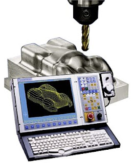
What is CNC ?
What is CNC? Basically, the CNC stands for Computer Numerical Control which refers to a computer controller that controls the movement of every axis of the machine using G codes instructions and drives the spindle or machine tool into a raw material to fabricate or to remove the unwanted material from workpiece more accurately without human intervention.
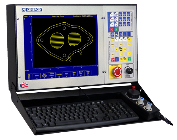
High performance and user-friendly CNC controller for milling applications
Photo by Centroid CNC
Fully integrated CNC machines will use G codes, M codes and others CNC programming languages codes such as F, S, N, X, Y, Z, A, B and C codes to control the overall machine.
G codes is a common name in the CNC programming language that begins with the letter G. Basically, the G codes tell the machine tool what type of action need to perform and trigger the CNC machine tools axis movement.
Typically, the CAM software such as Edgecam, Bob-CADCAM, Alphacam, MasterCAM, ProCAM 2, SurfCAM, Artcam and DelCAM may be used to generate the G codes files. The translators called post-processors will optimize the G codes output and it's user editable for further customization if needed.
The CNC milling machine simple programming language that use G codes and other CNC codes to perform drilling some holes and milling a circle pocket clean out.
; ICN_PATH = c:\intercon\test-run1.icn
; --- Header ---
N0001 ; CNC code generated by Intercon v2.61 Dev Test, Rev 8
; Description: test
; Programmer: vast
; Date: 11-Sep-2008
M25 G49 ; Goto Z home, cancel tool length offset
G17 G40 ; Setup for XY plane, no cutter comp
G21 ; millimeter measurements
G80 ; Cancel canned cycles
G90 ; absolute positioning
G98 ; canned cycle initial point return
; --- Tool #5 ---
;Tool Diameter = 6.0000 Spindle Speed = 1000
;d5
G49 H0 M25
G0 X0.0 Y0.0
N0002 T5 M6
S1000 M4
M8
G4 P1.00 ; pause for dwell
G43 D5
; --- Drill BHC ---
N0003 X20.0 Y0.0 Z2.54 H5
G81 X20.0 Y0.0 Z-1.0 R2.5 F100.0
X12.47 Y15.637
X-4.45 Y19.499
X-18.019 Y8.678
X-18.019 Y-8.678
X-4.45 Y-19.499
X12.47 Y-15.637
G80
; --- Circ Poc ---
N0004 X200.0 Y-1.0 Z2.54
G1 G91 X0.0 Y0.0 Z-2.54
X0.0 Y0.0 Z0.0 F300.0
X0.0 Y1.0 Z-1.0 F100.0
G2 X0.0 Y3.5 Z0.0 J1.75 F300.0
X-3.5 Y-3.5 Z0.0 J-3.5
X3.5 Y7.0 Z0.0 I8.75
X0.0 Y0.0 Z0.0 J-7.0 F400.0
X0.0 Y-7.0 Z0.0 J-3.5
G0 G90 X200.0 Y0.0 Z2.54
; --- End Prog ---
N0005 G49 H0 M25
X200.0 Y0.0
G40 ; Cutter Comp Off
M5 ; Spindle Off
M9 ; Coolant Off
G80 ; Cancel canned cycles
M30 ; End of program
The G codes generated by CENTROID's Intercon Conversational software used in Centroid CNC Milling Machine controller
CNC Machining Center
What is CNC machining center? The CNC machining center is a sophisticated CNC machine that can perform multiple machining operations with a verity of tools and operation methods by making used of several axes under fully integrated computer numerical control.
CNC Turning Machining Center
Photo by USOCA
The CNC Machining Center also known as CNC Machine Center. Most of machining centers are proven mechanical stability and high production efficiency. The machine centers are casted from high rigid cast iron through a series of procedures from back fire of blast furnace, normalizing, high frequency heat treatment to precision grinding process for outstanding material stability and assures long-term deformation-free performance, to increase cutting rigidity, machining accuracy, and to increase the overall stability of the machine.
The CNC machining center can be categorized into several categories base on type of machining center and machines function to cater your needs such as Vertical Machining Center, Horizontal Machining center, CNC Turning Center, CNC Router Center, column traverse type Vertical Machining Center, double column type Vertical Machining Center, high speed Vertical Machining Center, multi-function CNC Turning-Milling Machining Center etc.
CNC Horizontal Machining Center
Photo by HI-TECH Machine Tools
CNC Vertical Machining Center
Photo by TOS KUŘIM
Subscribe to:
Posts (Atom)